Mfr Part # ABX00087
ARDUINO UNO R4 WIFI
Arduino
License: General Public License Arduino
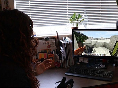
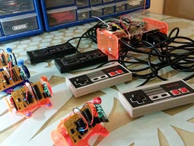
Gaming controllers are a great example of how physical inputs are translated into digital commands. In this project, you’ll build a simple USB Arduino game controller using the Arduino Uno R4, a two-axis joystick, and four push buttons.
When connected to your computer, the Arduino appears as a standard USB keyboard. Moving the joystick sends arrow-key inputs, while the buttons act as custom keys such as W, A, S, and D. Because most PC games already support keyboard controls, the controller works immediately without installing drivers or additional software.
This project is ideal for beginners who want to learn about USB HID (Human Interface Device) communication and build a practical gaming accessory.
Boards with native USB support, such as the Arduino Uno R4, can emulate keyboards, mice, and other HID devices. That means your microcontroller can send keystrokes directly to a PC over USB.
This approach offers several advantages:
No drivers required
Compatible with most PC games
Fully customizable controls
Simple hardware design
Easy to expand with more buttons or LEDs
Many makers on Reddit recommend using boards with native USB HID support for controller projects because they work as standard input devices across Windows, Linux, and macOS.
To build this controller, you will need:
1 × Perfboard or breadboard
The joystick provides analog X and Y position data, and the buttons provide digital inputs for additional game actions.
The joystick outputs two analog voltages:
X-axis controls left and right movement
Y-axis controls up and down movement
The Arduino reads these values and compares them to preset thresholds. When the joystick moves beyond those limits, the board sends the corresponding arrow-key press to the computer.
Each push button is connected to a digital input pin configured with INPUT_PULLUP. When a button is pressed, the pin goes LOW, and the Arduino sends a keyboard character.
VCC → 5V
GND → GND
VRx → A0
VRy → A1
Button 1 → D2
Button 2 → D3
Button 3 → D4
Button 4 → D5
Other terminal of each button → GND
No external resistors are needed because the internal pull-up resistors are enabled in software.
The joystick and buttons are mapped to the following keyboard inputs:
Left → Left Arrow
Right → Right Arrow
Up → Up Arrow
Down → Down Arrow
Button 1 → W
Button 2 → A
Button 3 → S
Button 4 → D
You can change these key assignments to match your favorite game.
#include <Keyboard.h>

// Joystick pins
const int joyX = A0;
const int joyY = A1;

// Button pins
const int buttonPins[4] = {2, 3, 4, 5};

// Dead zone thresholds
const int LOW_TH = 350;
const int HIGH_TH = 670;

// Button key mapping
const char buttonKeys[4] = {'w', 'a', 's', 'd'};

void setup() {
  for (int i = 0; i < 4; i++) {
    pinMode(buttonPins[i], INPUT_PULLUP);
  }

  delay(3000);          // Allow time for USB enumeration
  Keyboard.begin();
}

void loop() {
  int x = analogRead(joyX);
  int y = analogRead(joyY);

  // Horizontal movement
  if (x < LOW_TH)
    Keyboard.press(KEY_LEFT_ARROW);
  else
    Keyboard.release(KEY_LEFT_ARROW);

  if (x > HIGH_TH)
    Keyboard.press(KEY_RIGHT_ARROW);
  else
    Keyboard.release(KEY_RIGHT_ARROW);

  // Vertical movement
  if (y < LOW_TH)
    Keyboard.press(KEY_UP_ARROW);
  else
    Keyboard.release(KEY_UP_ARROW);

  if (y > HIGH_TH)
    Keyboard.press(KEY_DOWN_ARROW);
  else
    Keyboard.release(KEY_DOWN_ARROW);

  // Button handling
  for (int i = 0; i < 4; i++) {
    if (digitalRead(buttonPins[i]) == LOW)
      Keyboard.press(buttonKeys[i]);
    else
      Keyboard.release(buttonKeys[i]);
  }

  delay(10);
}Analog joysticks rarely sit at exactly their center value. Small fluctuations can cause unwanted movement if every reading is treated as input.
The dead zone solves this by defining a neutral range:
Values below 350 trigger movement in one direction
Values above 670 trigger movement in the opposite direction
Values in between are ignored
Adjust these thresholds if your joystick drifts when untouched.
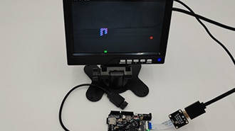
Upload the code to your Arduino Uno R4.
Connect the board to your PC.
Open a text editor.
Move the joystick and press buttons.
You should see the arrow keys and W/A/S/D characters appear.
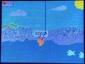
Once confirmed, open any game that supports keyboard controls and map the keys as needed.
This controller works well for:
Retro games
Arcade emulators
Platformers
Fighting games
Educational projects
Custom control panels
Because it behaves like a keyboard, it is compatible with virtually any game that accepts keyboard input.
Make sure you are using an Arduino board with native USB support and that the Keyboard.h library is included.
Increase the dead zone thresholds.
Verify that one side of each button is connected to ground.
Check for loose wiring or missing Keyboard.release() calls.
Once the basic controller is working, you can expand the design by adding:
More action buttons
Turbo-fire functionality
RGB LEDs
Vibration feedback
Wireless connectivity
3D-printed enclosure
This project demonstrates several useful embedded systems concepts:
Reading analog and digital inputs
USB HID communication
Keyboard emulation
Debouncing and dead zones
Human-machine interface design
Building a custom USB game controller is a fun and practical way to explore how hardware interacts with software. With only a handful of components, you can create a plug-and-play controller that works with thousands of PC games.
Whether you are reliving retro gaming memories or experimenting with custom input devices, the Arduino Uno R4 makes it easy to turn your ideas into a fully functional controller.